How much phase oversampling is needed

In MRI scans phase oversampling is often used to prevent phase warp-around (fold-over) artifacts. The scan is acquired with a expanded Field of View in phase-encoding direction, which is discarded during reconstruction. Due to the increased scan time we only want to use as little as needed. A naive view is, that everything contributing signal covered by the used coils must be included in the expanded Field of View. The depiction on Siemens MRI Scanners also suggest this. [1,2] As is shown below, the actually covered length is twice as big even for GRAPPA accelerated scans.
Theory
From the theory of the phase warp-around, it is clear, that anything outside of the FoV will appear beginning on the other edge of the FoV.
When using phase oversampling an area half of its size on both ends is discharged. Since the warp-around will start falling in the area of the other edge which is also removed during reconstruction, it will only enter the image when it is larger than it. Any warp-around artifact appearing there is of no consequence.
Thus the naive view is overly conservative and the actually suppressed range is twice as big. E.g. a phase oversampling of 30% (of the FoV size in phase encoding direction) effectively covers 30% in both directions (not only 15%).
Parallel Imaging
This consideration is only valid if the artefacts start appearing form the other edge of the image. For parallel imaging this is not necessarily the case, as can be seen with SENSE. For a SENSE factor of 2 the first artefacts appear in the middle of the FoV. But for GRAPPA no such aliasing has be reported.
It has been reported that sensitivity encoding (SENSE) reconstruction fails whenever the reconstructed FOV is smaller than the object being imaged. On the other hand, generalized autocalibrating partially parallel acquisition (GRAPPA) has been used success- fully to reconstruct images with aliasing in the reconstructed FOV, as in conventional imaging.
While the SENSE image is aliased in the middle of the FOV, the appearance of the aliasing in the GRAPPA image is exactly as it would be in conventional nonaccelerated imaging. No additional aliasing errors are observed. In our experience, this type of image appearance is common.
[3]
Experiment
The analysis of a test scan below will confirm these reports. [3,4]
Scan
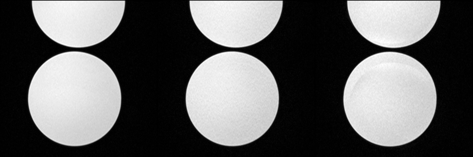
Two phantoms where scanned such that parts of the upper phantom in phase encoding direction where outside of the FoV and thus could cause warp-around artifacts. (The original intent was to use only the upper phantom, but due to insuficcient signal the second one had to be added.)
A scan with 30% phase oversampling, chosen such that the only phase warp-around would occur in the oversampled region was acquired without parallel imaging, GRAPPA and mSENSE (see image from left to right).
To observe and compare the aliasing a further scan without oversampling was performed.
The image for the 30% oversampling is a re-recon of the raw data without oversampling removal. Thus it depicts and confirms our understanding of phase oversampling and warp-around.

Result
For analysis a 1D line through the center of images in phase encoding direction was extracted.

It can be seen from the subtraction with the unaccelerated scan along the center in phase encoding direction, that, as expected, SENSE leads to artefacts even with 30% oversampling. GRAPPA on the other hand shows no significant deviation (shaded area +- 1 standard deviation).

The Signal to Noise ratio is similarly reduce for both accelerations. A factor of √2 is to be expected since only half of the k-space lines are acquired (the g factor can lead to a further reduction) [5]
For the SNR calculation the variance has to be estimated. This was achieved by running 5 identical scans from which the per pixel standard deviation can be estimated.

No spatial SNR distortion could be observed. Though parallel imaging is know to affect the noise distribution (independent of aliasing).
appendix
Scan Parameters
The Scan Parameters for GRAPPA and mSENSE were:
<ismrmrdHeader xmlns="http://www.ismrm.org/ISMRMRD" xmlns:xsi="http://www.w3.org/2001/XMLSchema-instance" xmlns:xs="http://www.w3.org/2001/XMLSchema" xsi:schemaLocation="http://www.ismrm.org/ISMRMRD ismrmrd.xsd">
[...]
 <encoding>
    <encodedSpace>
      <matrixSize>
        <x>512</x>
        <y>333</y>
        <z>1</z>
      </matrixSize>
      <fieldOfView_mm>
        <x>392.000000</x>
        <y>254.800003</y>
        <z>20.000000</z>
      </fieldOfView_mm>
    </encodedSpace>
    <reconSpace>
      <matrixSize>
        <x>512</x>
        <y>512</y>
        <z>1</z>
      </matrixSize>
      <fieldOfView_mm>
        <x>196.000000</x>
        <y>196.000000</y>
        <z>20.000000</z>
      </fieldOfView_mm>
    </reconSpace>
    <encodingLimits>
      <kspace_encoding_step_1>
        <minimum>0</minimum>
        <maximum>232</maximum>
        <center>116</center>
      </kspace_encoding_step_1>
[...]
    </encodingLimits>
    <trajectory>cartesian</trajectory>
    <parallelImaging>
      <accelerationFactor>
        <kspace_encoding_step_1>2</kspace_encoding_step_1>
        <kspace_encoding_step_2>1</kspace_encoding_step_2>
      </accelerationFactor>
      <calibrationMode>embedded</calibrationMode>
    </parallelImaging>
  <sequenceParameters>
    <TR>7.300000</TR>
    <TE>3.020000</TE>
    <TI>300.000000</TI>
    <flipAngle_deg>20.000000</flipAngle_deg>
    <sequence_type>Flash</sequence_type>
  </sequenceParameters>
  <userParameters>
    <userParameterLong>
      <name>EmbeddedRefLinesE1</name>
      <value>24</value>
    </userParameterLong>
[...]
  </userParameters>
</ismrmrdHeader>
Every scan contains five measurements. The non accelerated scan has the same parameters; except the acceleration.
ReRecon without Oversampling Removal
The raw data from the scanner was converted into the ISMRMRD format (siemens_to_ismrmrd). Then it could be reconstructed with Gadgetron.
To prevent oversampling removal the header of the raw data was changed as follows:
                <reconSpace>
                        <matrixSize>
                                <x>512</x>
-                               <y>512</y>
+                               <y>666</y>
                                <z>1</z>
                        </matrixSize>
                        <fieldOfView_mm>
                                <x>196.000000</x>
-                               <y>196.000000</y>
+                               <y>254.000000</y>
                                <z>20.000000</z>
                        </fieldOfView_mm>
                </reconSpace>
Further a remove oversampling configuration based on Generic_Cartesian_Grappa.xml without oversampling removal was used.
    <!-- RO oversampling removal -->
    <!--
    <gadget><name>RemoveROOversampling</name><dll>gadgetron_mricore</dll><classname>RemoveROOversamplingGadget</classname></gadget>
		-->
while the resulting reconstruction depicts the full FoV; the Matrix dimensions where interchanged. This was not further investigated.
Since hdf-view was broken on my Debian system, the images were extracted using silx
Data Analysis
For Data Anaysis with R the DICOM images were converted to 16-bit PNG files with dcm2pnm. For the subsequent statistics a normal distribution of the noise was assumed. This assumption is valid for high SNR [6,7].
Since the noise was calculated per pixel from the five measurements not signal dependence or correlation had to be considered.
References
[2] [Untersuchungs-Parameter. Phasen-Oversampling (Parameterkarten Routine, Geometrie - Allgemein) [ParaE11_14009]syngo MR E11
[3] Griswold, M. A., Kannengiesser, S. , Heidemann, R. M., Wang, J. and Jakob, P. M. (2004), Field‐of‐view limitations in parallel imaging. Magn. Reson. Med., 52: 1118-1126. doi:10.1002/mrm.20249
[4] Goldfarb, J. W. (2004), The SENSE ghost: Field‐of‐view restrictions for SENSE imaging. J. Magn. Reson. Imaging, 20: 1046-1051. doi:10.1002/jmri.20204
[5] McRobbie, D., Moore, E., Graves, M., & Prince, M. (2017). MRI from Picture to Proton. Cambridge: Cambridge University Press. doi:10.1017/9781107706958
[6] Den Dekker, A. J., & Sijbers, J. (2014). Data distributions in magnetic resonance images: a review. Physica Medica, 30(7), 725-741. doi:10.1016/j.ejmp.2014.05.002
[7] Aja‐Fernández, S. , Tristán‐Vega, A. and Hoge, W. S. (2011), Statistical noise analysis in GRAPPA using a parametrized noncentral Chi approximation model. Magn. Reson. Med., 65: 1195-1206. doi:10.1002/mrm.22701
Appendix Full FoV ReRecon Siemens
Notes for doing a full FoV retro recon on a Siemens scanner (i.e. include the part covered by oversampling in the reconstruction). The parameters were found using a diff from two xml parameter files from XBuilder/Twix of the base and target sequence.
2D Phase Oversampling
MEAS.sKSpace.dPhaseOversamplingForDialog  0.60000 → 0.0
MEAS.sKSpace.IPhaseEncodingLines          363     → 1.6*363 = 580.8
MEAS.sSliceArray.asSlice.0.dPhaseFOV      300     → 480
3D Slice Oversampling
MEAS.sKSpace.dSliceOversamplingForDialog  0.3333333 → 0.0
MEAS.sKSpace.IImagesPerSlab               192       → 1.33*192 = 255
MEAS.sSliceArray.asSlice.0.dThickness     153.6     → 1.33*153.6 = 204.288 (Adjusts HF FoV)